
One of the beauties of robotic ultrasonic testing technology is that it allows operators to see and measure things that humans alone cannot (e.g., precise wall loss in a boiler). However, this information isn’t particularly useful unless operators are able to—in simple terms—see exactly what the robot saw when it’s time to perform repair work. That’s where the critical nature of localization comes in.
In today’s blog, we’ll discuss the value of accurate localization and its significance to inspections, as well as different surveying technologies used to achieve localization in real-world applications and their applicability to asset inspections.
First…
What’s the Big Deal About Localization?
Localization identifies exactly where something is in relation to exactly where other things are. It’s very closely related to mapping; in essence, it is the position of the object relative to the map.
Precise localization allows operators to gather very accurate data regarding where a defect is on an asset by pinpointing its location. An important accompanying concept of localization is collection of year-over-year (YoY) data, or the ability of operators to correlate the measurements they take over time (which, historically, has been a big pain point in the industry). Without that consistency, operators don’t have an accurate picture about how a defect is progressing, or when the optimal time is to perform repair work.
So, considering inspections performed at different times using different techniques, in order to extract the most information, operators want to ensure they’re done at the same location in the asset. This allows for that important comparison of YoY data, and that can’t really be done without good localization.
With good localization, digital twinning can be used. Digital twinning is the result of using all the data that has been collected about your asset and building a computer model of it. This enables operators to use different functions to accelerate time to measure things like loss or erosion rates for predictive maintenance.
Localization techniques and technologies used today are largely borrowed from the surveying industry (think civil engineering, roads, bridges, GPS, etc.). While many are used in a wide range of everyday applications, many are not sufficient for asset inspections.
Localization 101
Two concepts to note when talking about localization surveying techniques are repeatability and reproducibility. Potato patato, right?
Actually—no. The two terms sound the same, but they are slightly different.
REPEATABILITY: Closeness of agreement between measured quantity values obtained by replicate measurements on the same or similar objects over a short period of time, under specific conditions of measurement, out of a set that includes the same measurement procedure, operators, measuring system, operating conditions and location.
REPRODUCIBILITY: Closeness of agreement between measured quantity values obtain by replicate measurements on the same or similar objects under specific conditions of measurement, out of a set that includes different locations, operators and measuring systems.
Confusing? Let’s break this down.
Say a robot traverses a surface and obtains a bad or low-quality scan. To get a quality measurement, the robot needs to drive back to that precise location and take another measurement. The ability of the inspection system to return to this exact location is repeatability.
Reproducibility refers to the ability of systems and operators to correlate their measurements with measurements taken by other systems and operators, at different times. This is where that YoY reproducibility discussed above becomes very important. If an operator wants to measure the degradation rate of an asset or perform predictive maintenance, they will want very good reproducibility of that localization (…among other things). These are metrics Gecko uses to evaluate and design the robotic localization systems for inspections.
Moving on and digging into surveying and technologies, think about the purpose of robots you might be familiar with, like warehouse robots or self-driving cars. Their ultimate goal is to arrive at the target destination without running into any obstacles, which, of course, is much different than an inspection robot. During every instance that an inspection robot takes a scan, it must know precisely where it is in the environment for that scan to be useful. Therefore, its position must be known continuously. With a self-driving car, it might take the same route every day along the commute, but change lanes at different times and locations each day, depending on traffic. It arrives at its destination and does not hit anything: mission accomplished.
From that example, it can be discerned the technologies commonly used for robotic localization won’t necessarily meet the requirements for robotic inspections. Rather, these technologies are closer to the field of surveying, which is the technique, procession, art and science of determining the terrestrial or three-dimensional positions of points and the distances and angles between them.
Surveying has existed for hundreds of years, used to build homes, roads and other infrastructure. To survey successfully, knowledge about the surrounding environment is imperative. Original tools used for surveying included chains and levels, then evolved to angle measurement devices like theodolites and sextants, and eventually, portable electronics with a wide variety of options including radio waves, ultrasonics, lasers and cameras for photogrammetry, which coordinate with some of the commonly used systems by civil engineers and surveyors: GNSS (essentially the international version of GPS) and robotic total stations.
Not only do inspection robots borrow technology from surveying, they borrow other concepts—in particular, control points. Control points refer to a specific location on the asset or environment: measured positions that are clearly identified.
When a robot is deployed for an inspection, its initial position is measured relative to the closest control point. Any subsequent measurements performed by the robot can then be referenced against that control point, so when it’s time for the operators or repair crews go in for evaluation of what the robot saw, they can use these control points to identify those locations.
Now, onto some different kinds of localization surveying techniques and their pros and cons.
Localization Surveying Techniques
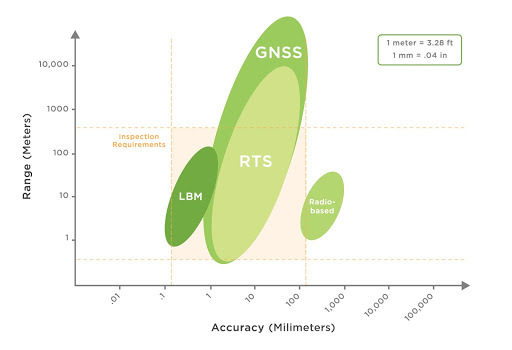
Radio-based: Radio-based technologies connect to a base receiver and are popular for many applications, such as inventory tracking. Some examples include Bluetooth Low Energy, RFID (Radio-frequency identification) and Ultra-wideband.
Pros: They are cheap, lightweight and scalable.
Cons: Their accuracy is generally limited to a few feet; they are not well-suited for robotic inspections.
GNSS/GPS: Global Navigation Satellite System and GPS are essentially the same—GPS is the most prevalent, American system, while GNSS is a general term to refer to any satellite constellation that provides positioning or navigation data (other countries with GNSS include Russia, China and the EU).
Pros: Because of the complexity and ingenuity of the systems, extraordinary high-performance localization can be achieved. They allow for high accuracy when satellites are spread out, and therefore work well for inspections such as fixed-roof tanks. They may supplement other methods by providing YoY control points in amenable locations, and in those cases, yield excellent performance and reproducibility, and good parameters when other systems are used for the actual inspection, such as Robotic Total Station (next discussed).
Cons: Satellite signals are weak and they're easily blocked by most obstacles. For example, the signals can't transmit through a wall or roof.
Robotic Total Stations (RTS): RTSs are commonly used by civil engineers. The fundamental operative principal is a very high-performance laser range finder that are mounted on two high-resolution rotation axes.
Pros: They have a very impressive accuracy of millimeters, over the range of miles. They allow for precise, remote operation and are excellent for identifying control points. They’re also great for measurements with few obstructions.
Cons: RTSs are expensive, require line of sight, and despite motorization, a human operator is required to recover from obstructions, as a rope or pipe support to a scaffold will block the range finder.
Light-Based Metrology (LBM), or indoor GPS (IGPS): Light-Based Metrology, or IGPS, is a highly accurate localization system based on rotating lasers that convert angle measurements from RTS into time measurements.
Pros: Cheaper to build than RTS, with RTS-level performance at short ranges. Robust to obstructions because laser beams sweep large area versus a single-point RTS laser, multiple setups can increase coverage and redundancy—i.e., eliminate shadows. When constructed properly, RTS-level performance can be achieved, in addition to orientation knowledge at short range. If the field of view from the receivers to the base station is obstructed, once back into the field of view, it can automatically recalculate its position using the timing of the laser light, without human interaction.
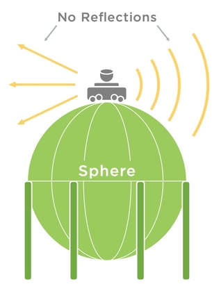
LIDAR (Light Detection and Ranging): LIDAR is a method for determining ranges or variable distances by targeting an object with a laser and measuring the time for the reflected beam to return from the surface. Some of the top uses of LIDAR includes land surveying, power line inspections, forestry and room or furniture measurements.
Pros: LIDAR is very popular, and great for conventional mobile robots because it’s onboard and doesn’t require external setups. These systems usually have great field of view and can roughly measure distances. They are great for detecting objects or obstacle avoidance.
Cons: Performance of a single LIDAR laser measurement is not comparable to an RTS. When used for localization, performance is entirely dependent on environment—they are very useful for localizing outdoors, but inside a boiler or tank, there are very few unique features for a LIDAR scan to bounce off. Therefore, they are difficult to use for localization purposes in these environments, especially for an external pipe inspection where there may be no objects nearby for emitted LIDAR scans to bounce off. In addition, these systems produce information extraneous to inspection, such as the size, shape and types of structures nearby, therefore system security or compromised operations are a potential issue.
It is important to note that all the systems above require line of sight from the sensor to the receiver to function properly. Try as we might, we can’t always make this happen, as inspection sites are very complex. So, what does that mean?
It means we need to carry some sensors onboard the robot, so they can never be obstructed and are always reporting information.
The two most common sensors used for this area are wheel odometry (these are on vehicles—motion sensors that estimate change in position over time) and inertial measurement units, or IMU (electronic devices that measure acceleration, angular rate and orientation—for example, your phone uses them to tell you it’s turned on its side).
These systems don’t rely on line of sight, and therefore will always report information. They can be integrated into localization calculations through a set of techniques called sensor fusion. Even though the information coming from a wheel odometer looks very different than that coming from an IMU or RTS, mathematically, we can combine them and our knowledge of the environment and robotics systems to produce the most optimal robotic locations. That equates to more information, and better results.
Finally, let's look at a couple of examples of localization technologies for asset inspections.
Case Study # 1: Non-Confined Space Entry Tank Floor
Good solution: Robotic Total Station (RTS)
An RTS is very suitable for this application, because generally, the insides of tanks have very few obstructions. RTS can be deployed outside the tank and still provide a great field of view inside the tank. In addition, because RTSs are so precise, they can give you the pin-size, high-resolution data that you want from your NDT inspection.
The icing on the cake is that RTS measures 3D position, meaning as your robot traverses the tank floor, it will also measure its elevation relative to the previous locations it traversed. It can also measure the contour of the tank floor to detect warping or settlement—a nice bonus, and a measurement that may not be captured at all with other types of localization for tank floor inspections.
Case Study #2: External Piping
Good solution: Light-Based Metrology (LBM)
If you consider the geometry of a pipe, there is no single location where an RTS will have a line of sight on all sides. While you can move the RTS through a process called resectioning to view a different angle of the pipe, it’s time-consuming and disrupts the flow of the inspection. Plus, piping generally has many support structures and other systems surrounding it, meaning there are a lot of obstructions for the RTS operator to drive around.
Therefore, LBM is the best option in this case. Multiple emitters can be placed around the asset with overlapping, complete coverage. In cases where there may not be an elevated position to put an LBM above a pipe, GNSS may work for the top side. Which, of course, is alright, as this is where sensor fusion comes into play and can combine the data.
Wrapping it Up
In conclusion, choosing the best localization solution for robotic ultrasonic inspections is crucial for reliability operations. When inertial systems are paired correctly with robotic controls, repeatability and reproducibility will allow operators to achieve the most accurate, useful YoY data for asset repair and predictive maintenance.
While there are tradeoffs involved in all the options on today’s market, the most appropriate, effective options—when deployed by experienced professionals—will produce valuable insight, potentially extend asset lifetime, increase reliability, streamline repair and maintenance, and the list goes on.
Gecko has experience with all the above technologies—contact our team for assistance in determining the best option for your asset inspection.
Want to learn more about localization? Check out our webinar, Locating Damage in the Dark!