
Ensuring pipeline and piping system integrity through planned inspections is crucial for operators to monitor damage mechanisms and avoid asset failure. Today’s market offers a variety of tools and technology to detect corrosion, cracks, leaks, and other damage, and ultimately, keep the pipeline safe to operate. This article will discuss the benefits and drawbacks of three pipeline inspection techniques for onshore industrial pipelines and piping systems: smart pipeline pigs, guided wave ultrasonics, and robotics. Depending on the scope, facility operators can decide which method, or combination of methods, is most suitable for the next inspection.
Pipeline Inspection Pigs
Originally, pigs, or pipeline inspection gauges, were not used for inspection purposes. Instead, they were solely used to clean out pipelines. The cylindrical devices were placed inside a pipe and then pulled or pushed through its length, scraping and removing buildup, dirt, or other debris. However, pigs began to evolve into “smart” models in the early 1960s with the addition of inline inspection capabilities. Besides being used for their original purpose of clearing pipelines and protecting flow integrity, intelligent pigging devices utilize nondestructive evaluation (NDE) technology to inspect pipes.

One significant benefit of pigging is inspecting the pipeline or piping system while it is in service. The pig is generally inserted into and extracted from the pipe at a specialized valve or pump station. The product flow moves the tool through the pipeline, collecting and recording data along the way. It is a suitable method for collecting data on long stretches of piping, covering several miles in a matter of days.
Data is collected through magnetic flux leakage (MFL) or ultrasonic testing (UT) techniques. MFL utilizes a magnetic field to detect magnetic flux leakage changes when there is a discontinuity in the metal caused by corrosion or pitting. Alternatively, the wide range of UT methods measures the time for the soundwave to travel to the metal and back to the transducer to determine wall thickness. More sophisticated UT techniques can detect cracking, pitting, laminations, and other damage.
Pipeline pigging has a few drawbacks. Logistically, the requirements of launching and receiving areas in the pipeline are limiting. Another is the possibility of the device getting stuck in the pipeline, which can occur when a pipe has not been previously pigged or has sharp bends, changes in the cross-section, or small diameter.
Additionally, both MFL and ultrasonic approaches have limitations. MFL can only indicate where a flaw or defect is located in the pipe. It cannot quantify the wall thickness. On the other hand, ultrasonics measure wall thickness but need a couplant to transmit the sound wave. If a pipe does not contain liquid, providing a couplant can add additional cost and time to the inspection. With both techniques, one major drawback is the time it takes to process and analyze the data. It can take weeks or months to receive the results from a pigging inspection, and the equipment’s condition may worsen during that time.
Guided Wave Testing
For pipelines or systems that are unpiggable or have support structures, guided wave testing (GWT) is a suitable method for inspecting an extended range of pipe from a single source. The study of guided wave propagation dates back to the 1920s, but its application as a pipeline inspection method was realized in the early 1990s.

A ring of ultrasonic transducers is placed around a pipe and transmits sound waves in both directions from the device. When the wave encounters corrosion or damage within the pipe wall, it echoes back to the transducers, and they automatically collect the data. Because the ring does not need to be in contact with the pipe, GWT can be used to find corrosion under insulation, a common yet difficult to detect damage mechanism.
Two benefits of guided wave techniques are speed and accessibility. It can efficiently inspect hundreds of meters of piping from one location while the equipment is in service. Additionally, the single source capabilities eliminate the need for scaffolding, and it can inspect buried, elevated, or supported pipes.
One limitation to GWT is its ability to characterize localized damage accurately. Another is the complicated inspection procedure. GWT requires skilled technicians to operate and analyze the data. However, the results are subjective from inspector to inspector. Because of these drawbacks, this technique should be coupled with other types of inspections to ensure accurate damage mechanism identification.
Pipeline Inspection Robots
The third pipeline inspection option, and perhaps the most efficient and accurate for high quality, quantitative data acquisition, is robotics. There are two broad categories, inline and outpipe inspection robots. Still, in general, they use a combination of NDT technology, cameras, and sensors to quickly collect and record imagery and data, enabling operators to pinpoint damage.
Inline robots crawl along the inside of piping and can even inspect unpiggable sections, such as vertical pipes. Several different inline inspection robots are on the market, but most require the pipeline to be taken out of service, which is a significant drawback. Similar to pipeline pigs, untethered inline inspection robots can move freely through the pipeline while it's in service. However, they have the same drawbacks as pigs, including the potential to get stuck, limited inspection time, and lengthy data turnaround.
Tethered devices are attached to cables that serve multiple functions, including power supply, couplant supply, control commands, and real-time data transmission to the technician. The cable can also serve as a safeguard against the device getting stuck or stranded, providing a means of retrieval. As for potential drawbacks, the tether limits the distance it can travel through the pipe.
Alternatively, outpipe or outside diameter robotic crawlers do not need inline access and can perform inspections while the pipeline remains in service. Some robots can even inspect pipes up to 500°F (260°C). Depending on the scenario, they can also significantly improve safety by eliminating scaffolding or rope access and exposing technicians to hazardous conditions.
Specialized outpipe robots have several benefits, including:
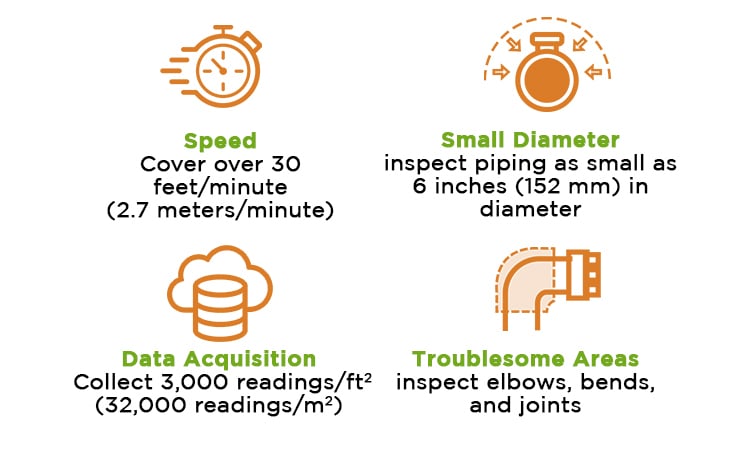
Limitations of outpipe robots are mostly related to accessibility. Because they require access to the outside diameter of the pipe, it must be above ground. Additionally, robots can be limited by support structures or the need for power or couplant supply.
While robotics, in general, tend to be more expensive than pigging or GWT, they can overcome some of the drawbacks. Robots can be used to inspect accessible pipelines unsuitable for pigging and produce quantitative data sets for developing repair and maintenance plans.
In conclusion, pipeline inspections are critical to avoid process interruptions, maintain asset integrity, regulatory compliance, and safety. Continually evolving inspection tools in today’s markets offer unique benefits and drawbacks that will vary according to each pipeline and its unique characteristics, including composition, thickness, length, damage susceptibility, and more. In the end, working with an experienced inspection technology provider will ensure operators select the tool and technology most suitable for their asset.